Car Cruise Control System Block Diagram

Block Diagram Of The Cruise Control System Download Scientific Diagram

3 Automobile Cruise Control Vehicle Speed Control Principles Of Operation And Implementation
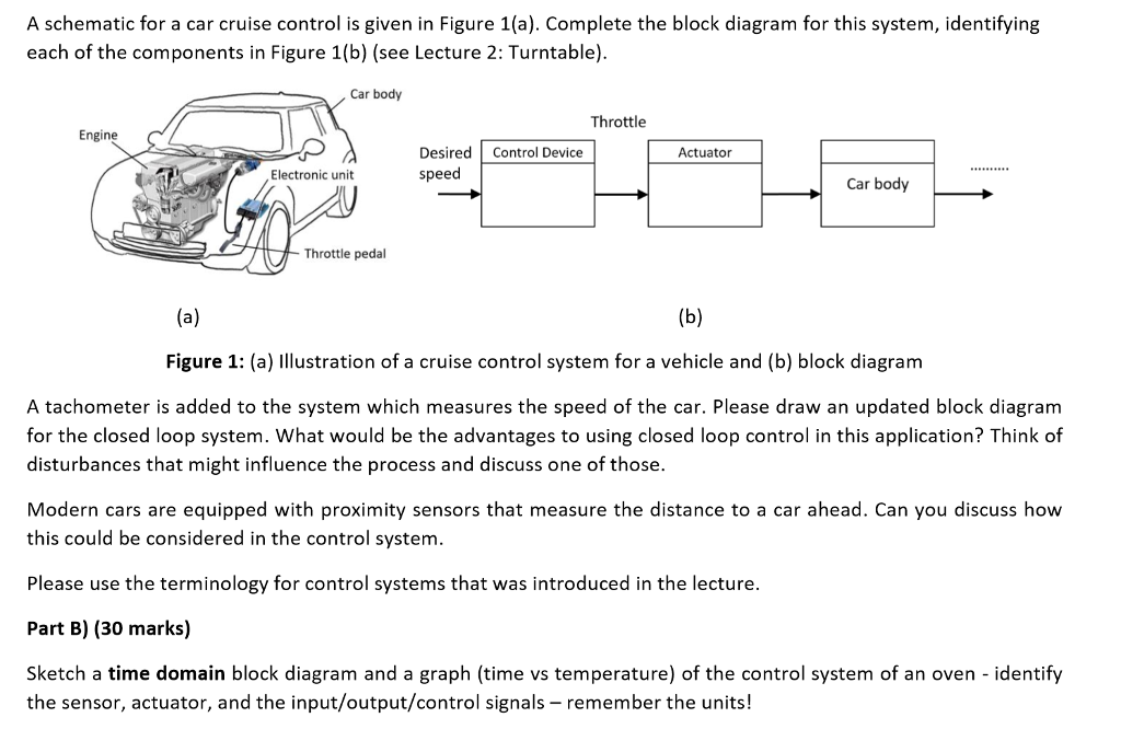
Solved A Schematic For A Car Cruise Control Is Given In F Chegg Com
Http Www Ajer Org Papers V5 06 E050602429 Pdf

Control Tutorials For Matlab And Simulink Cruise Control Frequency Domain Methods For Controller Design

Figure 2 From Modeling And Design Of Cruise Control System With Feedforward For All Terrian Vehicles Semantic Scholar
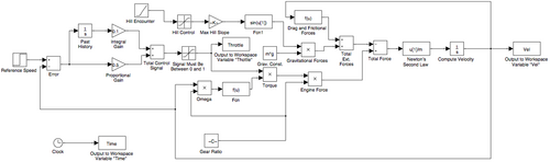
τ d4 3e a block diagram of the system is shown in figure 4 2.
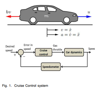
Car cruise control system block diagram. System model and parameters. There are several inputs. If on denotes that the car engine is turned on. Indication of how far the accelerator has been pressed.
1 the parameters used in this example are as follows. The transfer function model for the cruise control problem is given below. Design diagram and working explained. Speed set by the driver of the vehicle without the need to press the accelerator pedal this system is particularly useful while driving at a constant speed as it significantly reduces driver fatigue.
What remains is to find the closed loop system function h s v s r s. The command input represents the user input that is setting the desired vehicle velocity to v0 mph. To understand how the cruise control system works we will derive the equations for the closed loop systems described by equations d4 2eand d4 3esince the effect of the slope on the velocity is of primary interest we will derive an equation that tells how the velocity error. M vehicle mass 1000 kg b damping coefficient 50 n s m r reference speed 10 m s.
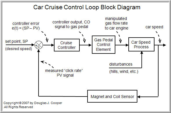
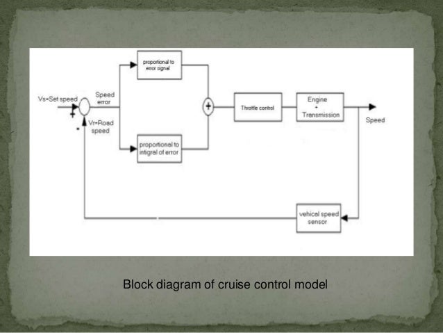
The cruise control system is only active if the engine is on. If on denotes that the cruise control system should maintain the car speed. Automatic cruise control is an excellent example of a feedback control system found in many modern vehicles. A pulse is sent for every revolution of the wheel.
Please see the cruise control. System modeling page for the derivation. This is the block diagram of the hardware for such a system.

Adaptive Cruise Controller Block Diagram Download Scientific Diagram

Pdf Comparison Of Pid Ga And Fuzzy Logic Controllers For Cruise Control System
The Components Of A Control Loop Control Guru
Engineer On A Disk
Csci 5854 Lecture 1 What Is Cps
Cruise Control Fbswiki

Antlion Optimizer Tuned Pid Controller Based On Bode Ideal Transfer Function For Automobile Cruise Control System Sciencedirect

Cruise Control Diagram Download Scientific Diagram
Cruise Control Systems
Hyundai Sonata Schematic Diagrams Cruise Control System Engine Electrical System
Operating Cruise Control Systems In Cars
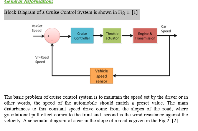
Solved General Information Block Diagram Of A Cruise Con Chegg Com
Kia Forte System Block Diagram Cruise Control System Engine Electrical System Kia Forte Td 2014 2018 Service Manual

